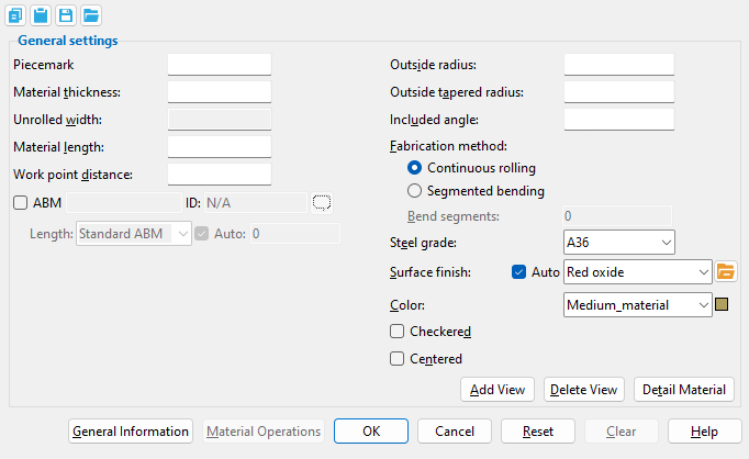
The Rolled Plate Material window
See on another page: Material Add Rolled Plate
- General Overview
- Tips and Tricks
- Related Tools
![]() Copy, Paste, Save, Load buttons:
Copy, Paste, Save, Load buttons:
- The position of these "form" buttons on the window tells you what settings they apply to. Click here for more information.
- You can
 Copy the settings on this window, then
  Paste those settings to a different edit window of the same type.
- You can
 Save the settings on this window to a file stored in a global folder that is used by your current version of SDS2. Give the file a name that will help other users identify its purpose. You can
  Load a saved file to replace the settings on this window (except Piecemark) with the settings that are stored in the file you select.
- When editing multiple windows at the same time, Paste and Load replace mixed entries to a single field with a single entry. Copy and Save ignore fields with mixed entries, treating them as if they have no entry or do not exist.
------ General settings ------
Piecemark: Blank or any character string (up to 61 characters). This is the submaterial piecemark.
If this field is left blank, then when this material is generated (after you press "OK"), SDS2 piecemarking looks for materials in the current Job that are physically identical to this material and assigns to this material the same mark assigned to those materials. If no matching materials are found, the material is assigned a piecemark using the appropriate material mark prefix listed for "Plate" in Home > Project Settings Fabricator > Piecemarking > Member and Material Piecemarking > the "Prefixes" tab.
Any 'character string' that you enter must be unique. Validation does not let you enter a piecemark that has already been assigned to materials. A piecemark entered here only applies if the material you are adding is unique -- if the material is exactly the same as previously added materials, the new material gets the piecemark of those previously added materials. On the other hand, if you are editing the material, all materials that are exactly like the material are re-assigned the unique mark you enter when the material is generated (after you press "OK"). The piecemark you enter remains a system piecemark, which means that it may be changed if you later edit a material just like this one and give that material a different piecemark.
Note 1: A submaterial mark is not yet assigned when this window opens for an add material operation. A piecemark is shown when you Edit Material or Review 2D Items. For the current quantity of materials assigned this piecemark, see the "Current quantity" listed on this material's General Information window.
Report Writer: MemberMaterial.Material.MinorMark
Advanced Selection: MinorMark
Parametric module: MinorMark
Material thickness: The thickness of this rolled plate. The thickness of a "Checkered" plate is measured exclusive of its raised pattern, along its Z material axis.
To enter gage plate: Type the 'gage number' followed by 'ga' (example: '4ga' is rewritten as '4GA' when you Tab out of the field). Right-click tells you the stored thickness (based on industry standards), from which the weight of the gage plate is calculated. Allowable gages are any whole number from 3 to 38. You can also enter an exact decimal thickness to get the gage (example: ' .1345 ' becomes ' 10GA ' when you Tab out of the field). The "Description" for a gage plate follows the format: 'plate prefix' + 'numberGA' + 'x' + 'width' (example: PL16GAx15 1/2 ).
Thickness precision: You can enter a plate "Material thickness" that is more precise than the "Dimension precision" that is set at Home > Project Settings Fabricator > Detailing > Drawing Presentaton. For example, if you enter '5/32' and the "Dimension precision" is '1/16', the thickness of the plate will be '5/32'. The thickness you enter will be reflected in the "Description". Be aware that the Ruler measures to whatever the "Dimension precision" is set to, which means that the plate's measured thickness may not exactly match its actual thickness.
Status Display: Material status > Material plate thickness
Report Writer: XXXXX.Thickness
Advanced Selection: Thickness
Parametric module: Thickness
Unrolled width: Read-only. This tells you the width of the material before it is rolled.
The "Unrolled width" is calculated from the rolled plate's "Outside radius", "Included angle", and the project setting "Rolled plate width dimension taken from" (Home > Project Settings > Fabricator > Detailing > Dimension Settings > Miscellaneous). The "Unrolled width" is used in the material "Description" found on the General Information window and in the "Description" shown in the member bill of material. The "Unrolled width" of the plate is also included in the plate section callout on the plate's submaterial detail.
Report Writer: XXXXX.Width
Advanced Selection: Width
Parametric module: Width
Material length: The distance of the rolled plate from outside edge-to-outside edge of the plate along its X material axis; perpendicular to the curvature of the plate.
Changing the material length results in the difference being added to/subtracted from the end of the rolled plate that is opposite to the first work point that was located. Doing this will also change the "Work point distance" accordingly. If the only operations you are performing on this material are defining an "Outside radius" and an "Included angle", the distance entered here will be the same as the "Work point distance".
Report Writer: XXXXX.OrderLength
Advanced Selection: OrderLength or PartLength
Parametric module: OrderLength or PartLength
Work point distance: The distance between the work points of this rolled plate.
Note: In most cases, this distance is the same as the "Material length", and changing the "Work point distance" works in exactly the same way as changing the "Material length". However, in the case of a tapered rolled plate (where a value for "Outside tapered radius" has been entered), this distance and the "Material length" will be different.
Report Writer: XXXXX.WorkpointSlopeDistance
Advanced Selection: WorkpointSlopeDistance
Parametric module: WorkpointSlopeDistance
Outside radius: The radius which the outside face of the plate is rolled to. The dimensional value entered here is referenced from the center of an imaginary circle to the outside face of the rolled plate. Add construction lines to the outer edges of the rolled plate to locate the center of the circle at the intersection of the construction lines. The value entered here will always apply to end of the rolled plate where the first work point was located. The outside radius at the opposite end will always apply the value entered in the "Outside tapered radius" field.
Note: Making a change to the "Outside radius" will directly affect the "Unrolled width" of the rolled plate.
Report Writer: XXXXX.RollOrBendRadius
Outside tapered radius: Similar to Outside radius, except it only applies to the end of the plate that is opposite to the end where the first work point was located. A value entered here that differs from the value of the "Outside radius" makes the rolled plate tapered from end-to-end. Enter a value here that matches the value of the "Outside radius" to make the rolled plate not tapered.
Report Writer: XXXXX.TaperRadius
Advanced Selection: TaperRadius
Parametric module: TaperRadius
Included angle: Any angle from .1 to 360 degrees. This is the number of degrees of the circle that is taken up by the arc of the outside face of the rolled plate. The entry you make here directly affects the "Unrolled width" of the rolled plate.
Report Writer: XXXXX.RolledOrBentAngle
Fabrication method: Continuous rolling or Segmented bending.
'Continuous rolling' sets the curve of the rolled plate to be continuously smooth.
'Segmented bending' causes the rolled plate to be a series of flat bend segments that together approximate a continuous curve around the "Outside radius" and the "Outside tapered radius". The bent corner of each segment is precisely located along the outside radius while the flat of each segment is not. The number of segments is the number entered to "Bend segments".
Bend segments: 0 or a quantity of segments from 3 to 400.
'0' (zero) produces the same result as "Continuous rolling".
An entry of '3 or greater' applies when "Segmented rolling" is selected. The more the segments, the smaller the bend angle between each segment, and the more closely the rolled plate approximates a continuous curve.
Steel grade: A36 or A572 or etc. This is the grade of steel of the rolled plate.
Setup: Home > Project Settings > Job > Material Grades > Plate Grades
Tip: Changing "Steel grade" "Color" and "Surface finish" do not cause the plate to be regenerated. This means that, if you change those settings only, material cut operations such as a Cut on Plane may, optionally, be preserved.
Report Writer: MemberMaterial.Material.SubMaterial.MaterialGradeDescription
Advanced Selection: MaterialGrade
Parametric module: MaterialGrade
Surface finish: None or Sandblasted or Red oxide or Yellow zinc or Gray oxide or Blued steel or Galvanized or Duplex Coating or Undefined 1 or Undefined 2 or Undefined 3 or Red oxide 2 or Any user added surface finish. This affects the colors of Solid members on erection views in the Drawing Editor . This also sets the color when Output material color is set to Surface finish for a VRML Export or a DWG/DXF Export. The Color (not Surface finish) sets the color of this material in Modeling .
| sand blasted | red oxide | yellow zinc | user surface finish 1 |
| gray oxide | blued steel | galvanized | user surface finish 2 |
To assign a different surface finish, you can drop-down the current surface finish and select the one you want, or you can press the
Auto ![]() or
or ![]()
If this box
is checked, the material surface finish follows what is set on the member level.
If the box
is not checked, the material surface finish can be changed to whatever is available in the list of surface finishes. If the surface finish changes from what the member level has set, the auto checkbox will be unchecked automatically. When the auto check box is unchecked, the member edit window shows an information tag which notifies the user that an attached material is not following what was set on the member level.
Note 1: Submaterial piecemarks can be split apart by surface finish. All surface finishes that do not have the Break Marks Material checked on can be applied to any like material with out the material splitting. If the Break Marks Material is checked on then only like materials with that specific surface finish can have the same piecemark, and because the submaterial marks differ so would the member's piecemark.
Note 2: When exporting a KISS file using "model" as the Data source surface finish data on the materials are compiled into the KISS download as follows, with a few exceptions (G=galvanized, N= none or sandblasted, P= others). Those exceptions are:
If the box for Finish routing in KISS export setup is set to a user routing
If the user has adjusted the Abbreviation for any of the default provided surface finishes
If you are using a user added surface finish
In these cases you will get what is provided in either the User routing, or the abbreviation field. For other exports it will always provide the abbreviation in the 'surface finishes' settings page.
Tip 1: Surface area is reported on the General Information window -- and this can be used to estimate the amount of coating required and its cost.
Tip 2: Changing Steel grade, Color, and Surface finish do not cause the plate to be regenerated. This means that, if you change those settings only, material fit operations such as a Fit Exact may optionally be preserved.
Report Writer: MemberMaterial.Material.SurfaceFinish
Setup: Surface Finish Settings
Color: A predefined color or a Custom Color. This is the approximate color of the rolled plate when it is displayed in one of the three solid forms.
The predefined colors are set up on the Predefined Colors window. The color swatch next to the list box (
) displays the color that is selected.
Select 'Custom Color' (last choice on the list) to launch your operating system's color picker and define any color you like.
Please note: Different colors may be assigned to materials that have the same submaterial piecemark. Changing a material's color does not trigger the material to be regenerated.
Report Writer: MemberMaterial.Material.MaterialColor3dRed
Report Writer: MemberMaterial.Material.MaterialColor3dGreen
Report Writer: MemberMaterial.Material.MaterialColor3dBlue
If this box is checked (
If the box is not checked (
Report Writer: XXXXX.CheckeredPlatePattern
Advanced Selection: CheckeredPlatePattern
Parametric module: CheckeredPlatePattern
Centered: ![]() or
or ![]() . This option positions the rolled plate with respect to the first work point located when this rolled plate was added.
. This option positions the rolled plate with respect to the first work point located when this rolled plate was added.
If this box is checked (
If the box is not checked (
Piecemarking: Two rolled plates -- one "Centered", the other not "Centered" -- may have the same submaterial "Piecemark". The two plates will have different submaterial mark index numbers.
|
Special Buttons for Detailing this Material (these do not appear for Add operations) |
||
|
|
|
|
| This button opens a window with a list of preset views. Each preset view that you select on this list is drawn on the submaterial detail when you Detail Submaterial. | This button opens a list of views you can delete. If the material has only one view, you get a warning instead of a list of views since you cannot delete the current view. | This button does a Detail Submaterial on this material. Newly added views are drawn on the detail. Deleted views are not drawn. |
General Information opens the General Information window, which provides additional information and settings that pertain to this material.
Tip: You can use the General Information window to change the material's X, Y, or Z global coordinates (and thus reposition the material within the 3D model).
Also: A Properties button at the bottom of the General Information window lets you Edit Properties for this material.
Material Operations opens the Material Operations window.
Tip: You can use the Material Operations window to delete or edit a stored material operation.
Note: Not all material operations are stored in the Material Operations window. Material Fit Exact, Material Fit Cope, Material Fit Notch, and Cut Layout are the only material operations that are stored here.
OK (or the Enter key) closes this window and applies the settings on it to the material(s).
Defaults: Even if you did not make any changes on this window, pressing OK causes many of the General settings on this window to be applied as the defaults for the next material of the same type that is added in your current session of Modeling.
If you opened this window to edit a single material (single-edit), the Change All Options & Warning List opens after you press the OK button. You can use that window to cancel your changes or, if other materials with the same submaterial piecemark exist, apply your changes to those other materials. Also, if a Cut On Plane or related cutting/bending/fit operation (that does not get stored in the Material Operations window) was previously done on this material, you are given the option to undo that operation.
If you opened this window to edit multiple materials (multi-edit), the Change All Options & Warning List does not open after you press the OK button. Also, if a Cut On Plane or related cutting/bending/fit operation (that does not get stored in the Material Operations window) was previously done on this material, you are not given the option to undo that operation.
Cancel (or the Esc key) closes this window without saving any changes.
Possibilities: If you are adding a new material, Cancel brings you back to the work point location step (step 2) in the add operation. For an edit material operation, Cancel ends the operation.
Tip: When you open this window to review information only -- and you do not want to set the defaults for the next-added rectangular plate -- the best way to close this window is to press Cancel.
Reset undoes all changes made to this window since you first opened it. The window remains open.
Note: The settings shown on this window when it first opens for the adding of a material are the settings of the last-added or last-edited material of the same type (unless you exit Modeling in the meantime).
Clear fills out this window with default settings when adding material. It is disabled during an Edit Material operation. These are the same defaults that are applied when the first new material is added during a session of Modeling in which no other material of the same type has been edited. For example, Clear automatically selects the default Steel grade and zeros out the all Left/Right End Settings.
- Material Add Rolled Plate
- Rolled Plate Edit window (Misc. member)
- Parametric information for Rolled Plate material
- Surface template (in the submaterial detail for rolled plate)
- Add Miscellaneous Member
- Miscellaneous Member Edit window (General settings and related topics)
- Miscellaneous Steel (Default misc. member types)
- Legacy Miscellaneous Member Edit window
- Settings on material windows for Add Legacy Miscellaneous Member
- Legacy Miscellaneous Steel (Legacy misc. member types)

